지난번에는 CC3000의 Smart Config 어플리케이션을 활용하면 편리하게 AP연결하는 방법에 대해 알아보았습니다.

오늘은 CC3000을 MCU에 포팅해보도록 하겠습니다. MCU는 STM32F4로 해보겠습니다.


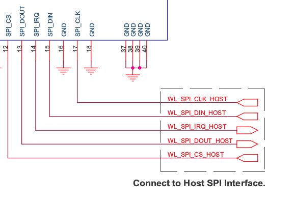
CC3000은 호스트 MCU와 SPI를 통해서 연결됩니다. 

그리고 IRQ 인터럽트(WL_SPI_IRQ_HOST)를 위한 GPIO 하나와 

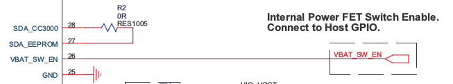
CC3000 모듈의 전원 on/off를 위한 GPIO 포트(VBAT_SW_EN)를 연결합니다.

아래와 같이 연결하면 됩니다.

Screenshot from 2014-11-29 16:31:22.png

Screenshot from 2014-11-29 16:32:01.png


CC3000의 포팅은 전반적으로 아래와 같은 구조로 진행됩니다. 

여기서 stm32와 연결하는 부분은 HCI와 SPI transport layer 부분만 포팅하면 됩니다. 

Screenshot from 2014-11-29 16:46:36.png

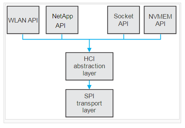
상위의 WLAN API 및 기타 API들은 하드웨어 포팅과는 크게 관련없이 네트워크 프로그래밍을 위해 사용됩니다.


포팅을 위해서는 아래 링크에서 TI에서 제공하는 Basic Wifi Application 소스로 작업할 수 있습니다.


http://processors.wiki.ti.com/index.php/CC3000_Wi-Fi_Downloads#Basic_Wifi_Application_and_Sample_Demos


설치를 하고 나면 설치된 경로에 예제 소스가 함께 있는데 그중에서 CC3000HostDriver와 CC3000 Spi 폴더를

stm32 프로젝트로 복사합니다. 그리고 BasicWifiApplication폴더는 포팅을 위해 참고만 합니다.


Screenshot from 2014-11-29 16:52:19.png

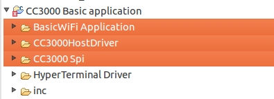
stm32 프로젝트 폴더에 복사한 뒤 디렉토리 구조입니다.

Screenshot from 2014-11-29 16:53:36.png

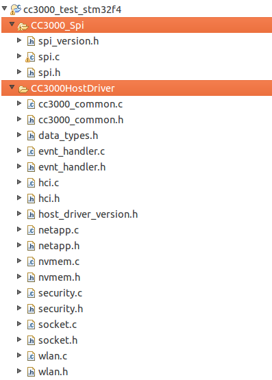
여기서 HostDriver 부분은 포팅을 위해 거의 수정할 부분이 없습니다. 주로 CC3000_spi폴더에서 수정합니다.

spi.c에서 아래 SPI와 GPIO 초기화 부분만 stm32로 포팅하고 SpiWriteDataSynchronous(), SpiReadDataSynchronous()를 수정합니다.

그리고 CC3000 IRQ 세팅을 위한 IntSpiGPIOHandler()도 stm32에 맞게 수정합니다.


아래는 stm32f4와 연결하기 위해 수정한 spi.c의 함수들입니다.


void pio_init()

{

GPIO_InitTypeDef GPIO_InitStructure;


/* CC3000_WIFI_CS_GPIO and CC3000_WIFI_EN_GPIO Peripheral clock enable */

RCC_AHB1PeriphClockCmd(CC3000_WIFI_CS_GPIO_CLK | CC3000_WIFI_EN_GPIO_CLK, ENABLE);


/* Configure CC3000_WIFI pins: CS output push-pull mode */

GPIO_InitStructure.GPIO_Pin = CC3000_WIFI_CS_GPIO_PIN;

GPIO_InitStructure.GPIO_Mode = GPIO_Mode_OUT;

GPIO_InitStructure.GPIO_OType = GPIO_OType_PP;

GPIO_InitStructure.GPIO_Speed = GPIO_Speed_50MHz;

GPIO_InitStructure.GPIO_PuPd = GPIO_PuPd_UP;//GPIO_PuPd_NOPULL;

GPIO_Init(CC3000_WIFI_CS_GPIO_PORT, &GPIO_InitStructure);


/* Configure CC3000_WIFI pins: Enable */

GPIO_InitStructure.GPIO_Pin = CC3000_WIFI_EN_GPIO_PIN;

GPIO_InitStructure.GPIO_PuPd = GPIO_PuPd_UP;//GPIO_PuPd_UP;//GPIO_PuPd_NOPULL;

GPIO_Init(CC3000_WIFI_EN_GPIO_PORT, &GPIO_InitStructure);


/* Disable CC3000 */

CC3000_Write_Enable_Pin(WLAN_ENABLE);//WiFi is enabled...

/* Deselect CC3000 */

CC3000_CS_HIGH();


CC3000_Interrupt_Enable();

}


CC3000의 IRQ를 위해 stm32의 EXTI 인터럽트를 초기화 합니다.

void CC3000_Interrupt_Enable(void)

{

GPIO_InitTypeDef GPIO_InitStructure;

EXTI_InitTypeDef EXTI_InitStructure;

NVIC_InitTypeDef NVIC_InitStructure;


/* CC3000_WIFI_INT_GPIO and AFIO Peripheral clock enable */

RCC_AHB1PeriphClockCmd(CC3000_WIFI_INT_GPIO_CLK, ENABLE);

/* Enable SYSCFG clock */

RCC_APB2PeriphClockCmd(RCC_APB2Periph_SYSCFG, ENABLE); //ported from stm32f4xx stdperiph lib


/* Configure CC3000_WIFI pins: Interrupt */

//ported from stm32f4xx stdperiph lib

GPIO_InitStructure.GPIO_Pin = CC3000_WIFI_INT_GPIO_PIN;

GPIO_InitStructure.GPIO_Mode = GPIO_Mode_IN;

GPIO_InitStructure.GPIO_OType = GPIO_OType_PP;

GPIO_InitStructure.GPIO_PuPd = GPIO_PuPd_UP;//GPIO_PuPd_NOPULL;

GPIO_Init(CC3000_WIFI_INT_GPIO_PORT, &GPIO_InitStructure);


/* Select the CC3000_WIFI_INT GPIO pin used as EXTI Line */

 /* Connect EXTI Line12 to PD12 pin */

SYSCFG_EXTILineConfig(CC3000_WIFI_INT_EXTI_PORT_SOURCE, CC3000_WIFI_INT_EXTI_PIN_SOURCE);//ported from stm32f4xx stdperiph lib

/* Clear the EXTI line pending flag */

EXTI_ClearFlag(CC3000_WIFI_INT_EXTI_LINE);


/* Configure and Enable CC3000_WIFI_INT EXTI line */

EXTI_InitStructure.EXTI_Line = CC3000_WIFI_INT_EXTI_LINE;

EXTI_InitStructure.EXTI_Mode = EXTI_Mode_Interrupt;

EXTI_InitStructure.EXTI_Trigger = EXTI_Trigger_Falling;

EXTI_InitStructure.EXTI_LineCmd = ENABLE;

EXTI_Init(&EXTI_InitStructure);


/* Enable and set CC3000_WIFI_INT EXTI Interrupt to the lowest priority */

NVIC_InitStructure.NVIC_IRQChannel = CC3000_WIFI_INT_EXTI_IRQn;

NVIC_InitStructure.NVIC_IRQChannelPreemptionPriority = EXTI15_10_IRQ_PRIORITY; //OLD: 0x00

NVIC_InitStructure.NVIC_IRQChannelSubPriority = 0x00; //OLD: 0x01

NVIC_InitStructure.NVIC_IRQChannelCmd = ENABLE;

NVIC_Init(&NVIC_InitStructure);

}


int init_spi(void) {

GPIO_InitTypeDef GPIO_InitStructure;

NVIC_InitTypeDef NVIC_InitStructure;

//DMA_InitTypeDef DMA_InitStructure;

SPI_InitTypeDef SPI_InitStructure;


/* Peripheral Clock Enable -------------------------------------------------*/

/* Enable the SPI clock */

SPIx_CLK_INIT(SPIx_CLK, ENABLE);


/* Enable GPIO clocks */

RCC_AHB1PeriphClockCmd(

SPIx_SCK_GPIO_CLK | SPIx_MISO_GPIO_CLK | SPIx_MOSI_GPIO_CLK,

ENABLE);


/* SPI GPIO Configuration --------------------------------------------------*/

/* GPIO Deinitialisation */

GPIO_DeInit(SPIx_SCK_GPIO_PORT);

GPIO_DeInit(SPIx_MISO_GPIO_PORT);

GPIO_DeInit(SPIx_MOSI_GPIO_PORT);


/* Connect SPI pins to AF5 */

GPIO_PinAFConfig(SPIx_SCK_GPIO_PORT, SPIx_SCK_SOURCE, SPIx_SCK_AF);

GPIO_PinAFConfig(SPIx_MISO_GPIO_PORT, SPIx_MISO_SOURCE, SPIx_MISO_AF);

GPIO_PinAFConfig(SPIx_MOSI_GPIO_PORT, SPIx_MOSI_SOURCE, SPIx_MOSI_AF);


GPIO_InitStructure.GPIO_Mode = GPIO_Mode_AF;

GPIO_InitStructure.GPIO_Speed = GPIO_Speed_50MHz;

GPIO_InitStructure.GPIO_OType = GPIO_OType_PP;

GPIO_InitStructure.GPIO_PuPd = GPIO_PuPd_DOWN;


/* SPI SCK pin configuration */

GPIO_InitStructure.GPIO_Pin = SPIx_SCK_PIN;

GPIO_Init(SPIx_SCK_GPIO_PORT, &GPIO_InitStructure);


/* SPI  MISO pin configuration */

GPIO_InitStructure.GPIO_Pin = SPIx_MISO_PIN;

GPIO_Init(SPIx_MISO_GPIO_PORT, &GPIO_InitStructure);


/* SPI  MOSI pin configuration */

GPIO_InitStructure.GPIO_Pin = SPIx_MOSI_PIN;

GPIO_Init(SPIx_MOSI_GPIO_PORT, &GPIO_InitStructure);


/* SPI configuration -------------------------------------------------------*/

SPI_I2S_DeInit(SPIx);

SPI_InitStructure.SPI_Direction = SPI_Direction_2Lines_FullDuplex;

SPI_InitStructure.SPI_DataSize = SPI_DataSize_8b;

SPI_InitStructure.SPI_CPOL = SPI_CPOL_Low;

SPI_InitStructure.SPI_CPHA = SPI_CPHA_2Edge; //SPI_CPHA_1Edge;

SPI_InitStructure.SPI_NSS = SPI_NSS_Soft;

SPI_InitStructure.SPI_BaudRatePrescaler = SPI_BaudRatePrescaler_4;//SPI_BaudRatePrescaler_32;

SPI_InitStructure.SPI_FirstBit = SPI_FirstBit_MSB;

SPI_InitStructure.SPI_CRCPolynomial = 7;


SPI_InitStructure.SPI_Mode = SPI_Mode_Master;

SPI_Init(SPIx, &SPI_InitStructure);


/* Enable the SPI peripheral */

SPI_Cmd(SPIx, ENABLE);

}

void
SpiReadDataSynchronous(unsigned char *data, unsigned short size)
{
long i = 0;
unsigned char *data_to_send = tSpiReadHeader;
for (i = 0; i < size; i ++)
{
while (SPI_I2S_GetFlagStatus(SPIx, SPI_I2S_FLAG_TXE) == RESET);
SPI_I2S_SendData(SPIx, data_to_send[0]);
while (SPI_I2S_GetFlagStatus(SPIx, SPI_I2S_FLAG_RXNE) == RESET);
data[i] = SPI_I2S_ReceiveData(SPIx);
}
//original codes ....
/*long i = 0;
unsigned char *data_to_send = tSpiReadHeader;

for (i = 0; i < size; i ++)
{
while (!(TXBufferIsEmpty()));
//Dummy write to trigger the clock
UCB0TXBUF = data_to_send[0];
while (!(RXBufferIsEmpty()));
data[i] = UCB0RXBUF;
}*/
}

void
SpiWriteDataSynchronous(unsigned char *data, unsigned short size)
{
while(size){
while (SPI_I2S_GetFlagStatus(SPIx, SPI_I2S_FLAG_TXE) == RESET);
SPI_I2S_SendData(SPIx, *data);
while (SPI_I2S_GetFlagStatus(SPIx, SPI_I2S_FLAG_RXNE) == RESET);
SPI_I2S_ReceiveData(SPIx);
size --;
data++;
}
//original codes ....
/*while (size)
{  
while (!(TXBufferIsEmpty()));
UCB0TXBUF = *data;
while (!(RXBufferIsEmpty()));
UCB0RXBUF;
size --;
data++;
}*/
}

void SpiResumeSpi(void)
{
//
//Enable CC3000 SPI IRQ Line Interrupt
//
NVIC_EnableIRQ(CC3000_WIFI_INT_EXTI_IRQn);  //it works ok

}

void SpiPauseSpi(void)
{
//
//Disable CC3000 SPI IRQ Line Interrupt
//
NVIC_DisableIRQ(CC3000_WIFI_INT_EXTI_IRQn);
}

void IntSpiGPIOHandler(void)
{
if (sSpiInformation.ulSpiState == eSPI_STATE_POWERUP)
{
//This means IRQ line was low call a callback of HCI Layer to inform
//on event
  sSpiInformation.ulSpiState = eSPI_STATE_INITIALIZED;
}
else if (sSpiInformation.ulSpiState == eSPI_STATE_IDLE)
{
sSpiInformation.ulSpiState = eSPI_STATE_READ_IRQ;

/* IRQ line goes down - we are start reception */
ASSERT_CS();

// Wait for TX/RX Compete which will come as DMA interrupt
SpiReadHeader();

sSpiInformation.ulSpiState = eSPI_STATE_READ_EOT;

SSIContReadOperation();

}
else if (sSpiInformation.ulSpiState == eSPI_STATE_WRITE_IRQ)
{
SpiWriteDataSynchronous(sSpiInformation.pTxPacket,
sSpiInformation.usTxPacketLength);

sSpiInformation.ulSpiState = eSPI_STATE_IDLE;

DEASSERT_CS();
}
#if 0 //original codes
//Pending is cleared in first level of ISR handler
if (!tSLInformation.ReadWlanInterruptPin())
{
   switch(sSpiInformation.ulSpiState)
   {
   case eSPI_STATE_POWERUP:
       sSpiInformation.ulSpiState = eSPI_STATE_INITIALIZED;
     break;
        case eSPI_STATE_IDLE:
SetState(eSPI_STATE_READ_IRQ, eAssert);
SpiIO(eRead, sSpiInformation.pRxPacket, arraySize(spi_readCommand), FALSE);
 break;
case eSPI_STATE_WRITE_WAIT_IRQ:
sSpiInformation.ulSpiState = eSPI_STATE_WRITE_PROCEED;
 break;
default:
 break;
   }
}
#endif
}

그리고 CC3000 IRQ 인터럽트는 EXTI 핸들러를 이용해서 처리합니다. 보통 stm32 펌웨어 소스의 stm32f4xx_it.c에서 수정합니다.

/*******************************************************************************
 * Function Name  : EXTI15_10_IRQHandler
 * Description    : This function handles EXTI15_10 interrupt request.
 * Input          : None
 * Output         : None
 * Return         : None
 *******************************************************************************/
void EXTI15_10_IRQHandler(void)
{
/*
 *   CC3000 IRQ Handler
 * */
if (EXTI_GetITStatus(CC3000_WIFI_INT_EXTI_LINE) != RESET)//
{
/* Clear the EXTI line pending bit */
EXTI_ClearITPendingBit(CC3000_WIFI_INT_EXTI_LINE);

SPI_EXTI_IntHandler();
}

}
주로 위와 같은 소스를 수정하면 어느정도 HCI layer 부분은 포팅이 됩니다.
그리고 아래와 같이 init함수를 만들어서 CC3000을 초기화 합니다. 
이부분은 basic_wifi_application.c 소스를 조금 수정했습니다.

//*****************************************************************************
//
//! initDriver 
//!
//!  @param  None
//!+
//!  @return none
//!
//!  @brief  The function initializes a CC3000 device and triggers it to
//!          start operation
//
//*****************************************************************************
int initCC3000Driver(void) {
// Init GPIO's
pio_init();

// Init SPI
init_spi();  

//Delay(100);

wlan_init(CC3000_UsynchCallback, sendWLFWPatch, sendDriverPatch,
sendBootLoaderPatch, CC3000_Read_Interrupt_Pin,
CC3000_Interrupt_Enable, CC3000_Interrupt_Disable,
CC3000_Write_Enable_Pin);

// Trigger a WLAN device
wlan_start(0);

// Mask out all non-required events from CC3000
wlan_set_event_mask(
HCI_EVNT_WLAN_KEEPALIVE | HCI_EVNT_WLAN_UNSOL_INIT
| HCI_EVNT_WLAN_ASYNC_PING_REPORT);

ucStopSmartConfig = 0;

return (0);
}
wlan_init에서 넘겨주는 함수와 전역 변수들은 모두 basic_wifi_application.c를 참고합니다.
이렇게 해서 main.c에서 initCC3000Driver()를 수행하면 CC3000이 초기화되고 AP연결을 위해서는 StartSmartConfig()를 수행합니다. 
여기서 PE1번 IO로 상태 LED를 컨트롤합니다. Smart Config를 위해 대기중일때는 LED를 깜빡입니다.
void StartSmartConfig(void) {
ulSmartConfigFinished = 0;
ulCC3000Connected = 0;
ulCC3000DHCP = 0;
OkToDoShutDown = 0;

// Reset all the previous configuration
wlan_ioctl_set_connection_policy(DISABLE, DISABLE, DISABLE);
wlan_ioctl_del_profile(255);

//Wait until CC3000 is disconnected
while (ulCC3000Connected == 1) {
Delay_Microsecond(10);  //0.041us * 100 ~= 5 us
hci_unsolicited_event_handler();
}

// Start blinking LED6 during Smart Configuration process
GPIO_ResetBits(GPIOE, GPIO_Pin_1);
wlan_smart_config_set_prefix((char*) aucCC3000_prefix);
GPIO_SetBits(GPIOE, GPIO_Pin_1);

// Start the SmartConfig start process
wlan_smart_config_start(1);

GPIO_ResetBits(GPIOE, GPIO_Pin_1);

// Wait for Smartconfig process complete
while (ulSmartConfigFinished == 0) {
Delay(200); //0.041us * 6000000 ~= 0.2 sec
GPIO_ResetBits(GPIOE, GPIO_Pin_1);

Delay(200);
GPIO_SetBits(GPIOE, GPIO_Pin_1);

}

// create new entry for AES encryption key
nvmem_create_entry(NVMEM_AES128_KEY_FILEID, 16);

// write AES key to NVMEM
aes_write_key((unsigned char *) (&smartconfigkey[0]));

// Decrypt configuration information and add profile
wlan_smart_config_process();

// Configure to connect automatically to the AP retrieved in the
// Smart config process
wlan_ioctl_set_connection_policy(DISABLE, DISABLE, ENABLE);

// reset the CC3000
wlan_stop();

//__delay_cycles(6000000);
Delay(200);

wlan_start(0);

// Mask out all non-required events
wlan_set_event_mask(
HCI_EVNT_WLAN_KEEPALIVE | HCI_EVNT_WLAN_UNSOL_INIT
| HCI_EVNT_WLAN_ASYNC_PING_REPORT);
}
상기 함수에서 Delay부분은 stm32의 systick을 활용하면 쉽게 구현이 가능합니다.
그리고 이더넷 테스트를 위해서는 socket(), sendto(), bind(), recvfrom() 등의 기존 소켓 프로그래밍에서 쓰던 API와 동일하게 사용가능합니다.